
![]()
Description.
A two channel digital volume control circuit based on IC MAX5486 is shown here. MAX5486 is a 40K dual digital volume / balance controller that has a pushbutton interface. The IC has a built in bias voltage source that eliminated the need of an external circuitry for the same purpose and thereby by reduces external parts count. The IC also has an LED status indicator driver circuit which can be used for driving the status indicator LEDs which indicates the volume level and balance level. The IC can be operated from a single or dual power supply and is available in 24 pin TSSOP package. The volume control circuit based on MAX5486 can be applied in a lot applications like personal audio systems, hand held audio devices, home theatre systems, car audio systems, computer audio systems etc.
Circuit diagram with Parts list.
Circuit description.
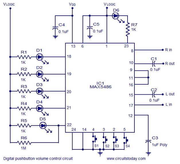
The right channel input is applied to the pin8 (high terminal (HR) of first internal digital potentiometer of the IC) and left channel input is applied to the pin17 (high terminal (HL) of the second internal digital potentiometer of the IC). Low terminals (pin 9 and 6) of the internal potentiometers are shorted and connected to the mid bias voltage output (pin11) of the IC. The right channel output is available at the buffered wiper terminal (pin10) of the first internal potentiometer and left channel output is available at the buffered wiper terminal of the second internal potentiometer of the IC. A 1uF capacitor is connected from the bias generator bypass (pin12) to ground. The purpose of this capacitor is noise bypassing. The purpose of capacitors C4 and C5 are to bypass noise from the VDD and VLOGIC sources. This improves the overall stability and performance of the circuit.
LEDs D1 to D5 are the status indicator LEDs which indicates the current volume and balance levels. R1 to R5 limits current through the corresponding LEDs. 1M resistor R6 is meant for activating the status indicator LED drivers. LED D6 represents the current operation mode of IC. When it glows, the IC is in balance control mode and when it is off, the IC will be in volume control mode. Resistor R7 limits the current through LED D6. In the volume control mode the status LEDs work just like a bar graph display indicating the current volume. In the balance control mode, the centremost LED alone glows when there is a centred balance. In the mute mode, all status indicator LEDs remain OFF.
Push button switches S1 to S4 are used for controlling the circuit. Pressing S1 will push the IC into mute mode. Push button S4 can be used for selecting between volume control mode and balance control mode and LED D6 indicated it. Push button S2 and S3 are used for increasing and decreasing the volume in the volume control mode and shifting the balance to left and right in the balance control mode. The Vss pin of the IC is grounded because single supply operation is employed in this circuit. Shutdown pin (pin6) is tied to the VLOGIC source for disabling the shutdown function. Connecting the shutdown pin to the ground will drive the IC to the shutdown mode.
The output of the MAX5486 is sufficient enough to drive standard high impedance headphones. For driving low impedance headphones or speakers an amplifier stage must be added to the output. The maximum power dissipation of MAX5486 is 675mW and consider this point while selecting the loads.
Notes:
- The circuit must be assembled on a good quality PCB.
- Use 5V DC for powering the circuit (both VLOGIC and VDD).
- The power supply must be well regulated and free from noise.
- Switches S1 to S4 are used for controlling the circuit.
- LED D1 to D5 are status indicators.
- An additional amplifier stage is required for driving low impedance loads.
![]()
